


scan test

Copyright © 2025
Scan Tests
To test a specific module within the chip we will need to control its inputs and observe its outputs
Internal nodes aren’t reachable for direct control or observation which challenge the test coverage
SCAN DFT:
- Is a DFT technique to enable testing internal nodes and increase test-ability/coverage
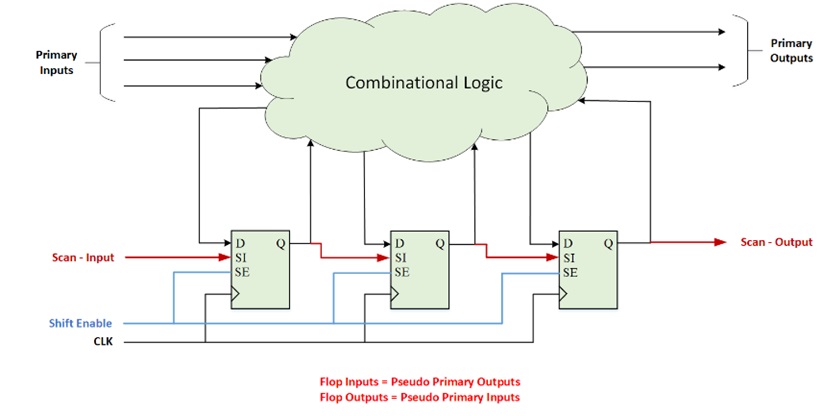
- Scan technique depends on the fact that the majority of our circuits are synchronous pipelines that contain CLB (combinational logic blocks) are sandwiched between registers/Flops
- We need to provide full controllability to the CLB’s inputs and full observability to CLB’s outputs
- Scan Insertion: means to add or modifying design’s circuitry to enable Scan technique by converting design Flip Flop to a Scan Flop and connecting all Scan Flops to form Scan Chain
- Converting Regular Flop to Scan Flop:
All regular flip flops (FF) in the design are converted into scan flip flops (SFF) by adding
-
- A multiplexer at its input
- Two new signals:
- SI (Scan Input)
- SE (Shift Enable) An external pin (controllable) connected to all scan flops.
- [SO, (Scan Output) – optional is same FF output
see image in next page
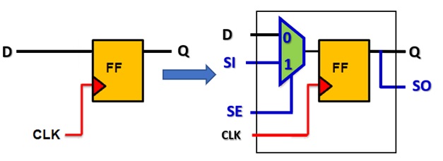
Scan-FF modes: it has two modes which based SE (Shift Enable) pin:
- When SE = ‘0’ Normal mode (non scan) each FF passes its D input to its Q output
- When SE = ‘1’ Test mode (Scan), Shift enable mode:
- The FFs are functioning as Shift FF: Scan FFs are functioning as a shift register
- Each of the SFF gets its SI input and pass it to SO/Q output
Scan test scenario: Scan chain operation involves three stages: Scan-in, Scan-capture & Scan-out.
Scan-in (Shift In): SE=’1’ Scan mode, shift mode where all SFFs are loaded with an input test vector with N cycle as number of SFFs
Scan-capture: SE = ‘0’ normal mode where FFs get their inputs from the CLB. one clock pulse (also, called the capture pulse) is allowed to excite the CLB. The output is captured at the second flop.
Scan-out (Shift Out): SE = ‘1’ Shift mode. Data is shifted out and the signature is compared with the expected signature.
the next image shows the sequence of events that take place during scan-shifting and scan-capture.
Published: Jan 7, 2025
Latest Revision: Jan 7, 2025
Ourboox Unique Identifier: OB-1634389
Copyright © 2025
![]()
 Skip to content